 airbrakecompressor
What the sensor and tone ring actually do
An ABS wheel speed sensor is a small magnetic pickup mounted in the wheel end that reads the teeth of a toothed ring — the tone ring, also called an exciter ring or pole wheel — turning with the hub. As each tooth passes the sensor tip it disturbs the magnetic field and induces an AC voltage in the sensor coil; the frequency of that voltage rises and falls with wheel speed. The ABS controller compares the signals from all monitored wheels many times per second, and when one wheel decelerates faster than the others it commands the ABS modulator valve to hold or dump air from that brake chamber until the wheel spins back up.
Most heavy-vehicle sensors are passive variable-reluctance units: two wires, no supply voltage, no electronics inside. That simplicity is why they last, and also why they are so sensitive to how they are mounted. The same wheel speed signal usually feeds traction control, stability control, and on many chassis the speedometer and engine electronics as well, so one bad wheel end can throw several unrelated-looking faults.
Tone rings on trucks and trailers are commonly 100-tooth, though 60- and 80-tooth rings exist depending on the wheel end. The controller is programmed for the tooth count and tire size, which is why mismatched hubs, wrong rings, or badly mismatched tire diameters side to side can produce speed comparison faults with no hardware failure at all.
Air gap: where most sensor faults start
Because the sensor makes its own voltage, output falls off quickly as the gap between the sensor tip and the ring teeth grows. Too much gap and the signal is too weak at low speed, which shows up as ABS activating at a crawl, dropping out, or logging intermittent codes that clear on a road test. The general limit is on the order of 0.04 in (1 mm) or less, and many wheel-end makers want it tighter — check the spec for the axle you are working on.
There are no shims. The sensor slides in a spring clip or clamping sleeve with a deliberate interference fit, and the setting procedure is mechanical:
- Make sure the clip and bore are clean, and that the clip is not corroded, spread, or spinning in the bore. A tired clip will not hold the sensor and the gap opens up on the first pothole.
- Apply only the wheel-end manufacturer's approved sensor lubricant to the sensor body and clip. Do not pack the tip with grease or use a lubricant that attacks the cable jacket.
- Push the sensor all the way in by hand until it bottoms against the tone ring — zero clearance.
- Rotate the wheel. The ring's natural runout backs the sensor off to its running clearance by itself.
- Route and clip the lead with slack at the steering knuckle or suspension, away from the tire, brake drum, and any hot or moving part.
If the sensor will not hold position, stop and check wheel bearing adjustment. Excess endplay lets the hub walk on the spindle and hammers the sensor back out of the bore; industry practice keeps endplay to a few thousandths of an inch, so any noticeable rock at the wheel needs to be corrected before the sensor is blamed.
Symptoms of a failed sensor or damaged ring
| What you see | Likely cause | First check |
|---|---|---|
| ABS lamp on steady, code stored for one wheel | Open sensor, open lead, or sensor pushed out of the bore | Resistance at the connector, then push the sensor back in and retest |
| Intermittent code that sets only at road speed | Chafed lead, corroded connector, or ring runout | Wiggle test the harness, compare live wheel speeds on a scan tool |
| ABS cycles or drops out at very low speed | Excessive air gap, weak output | AC voltage with the wheel spun by hand |
| One wheel reads zero or erratic while others are normal | Missing or broken ring teeth, packed debris in the teeth | Pull the hub cover or drum and inspect the ring |
| Trailer ABS lamp on the roadside of the trailer stays lit | Trailer sensor, ring, or the auxiliary power circuit through the seven-way | Confirm power and ground at the trailer ECU before pulling wheel ends |
| Traction or stability lamp with the ABS lamp | Shared wheel speed input lost | Read all codes; do not chase the secondary lamp |
An ABS fault does not disable the foundation brakes. The system reverts to normal pneumatic braking with the compressor, governor and reservoirs working as always — cut-out around 120-135 psi, cut-in around 100-110 psi, fully charged near 120 psi. What you lose is wheel-by-wheel modulation, and on a roadside inspection an illuminated lamp is a documented defect. See what the ABS warning light means before deciding a truck can stay in service.
Test values worth knowing
| Test | Typical result | What a bad reading means |
|---|---|---|
| Coil resistance across the two leads | Commonly a few hundred to a few thousand ohms, depending on the maker | Open or shorted winding; replace the sensor |
| Insulation to chassis ground | Generally above about 100,000 ohms | Moisture or a chafed lead grounding the circuit |
| Output with wheel turned by hand, roughly half a turn per second | At least about 0.2 volts AC on most specifications | Air gap too wide, ring damage, or a weak sensor |
| Live wheel speed on a scan tool, wheels off the ground | Left and right within a few tenths of an mph of each other | Ring tooth damage or mismatched tone ring tooth count |
Always confirm the actual numbers against the ABS supplier's service data for the system on the vehicle. Do the electrical checks at the sensor connector first, then repeat at the ECU connector — the difference tells you whether the fault is the sensor or the harness between them.
Inspecting the tone ring
Tone rings are pressed onto the hub or bolted to it, and on some wheel ends they are machined into the hub itself. Look for cracked or spread rings, chipped or missing teeth, rust scale that has bridged the tooth gaps, and metal filings or brake dust packed solid between teeth. A ring that has spun on the hub or lifted on one side changes the air gap once per revolution and produces exactly the kind of intermittent fault that clears on the shop floor. Clean the teeth with a non-metallic brush; a damaged ring is not repairable and is replaced with the hub or as a pressed component, following the wheel-end maker's procedure and bearing adjustment spec.
Replacement notes
Never pull a sensor out by its cable, and never re-use a sensor that has been dragged out of a seized clip — the tip and the body seal are easily damaged. Replace the clamping sleeve whenever it is corroded or no longer grips. Route the new lead exactly where the original ran and secure it so suspension travel does not stretch it. Match the sensor by body diameter, cable length, and connector type; a straight or 90-degree body matters as much as the electrical spec. For heavy-vehicle wheel ends, VADEN Original supplies OE-grade ABS wheel speed sensors cross-referenced to the common truck and trailer applications. When the job is done, clear the codes, road test above the speed at which the fault set, and confirm the lamp goes out and stays out. For background on how the whole system is laid out, including sensor and modulator configurations such as 4S/4M and 4S/2M, see our overview of ABS on air brake systems.
If a wheel end is apart for bearing or seal work, set the sensor last, after the hub is torqued and endplay is verified. Setting it first guarantees you will set it twice.
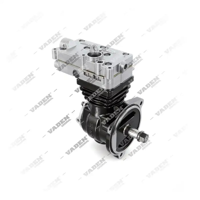
Need the part, not just the answer?
OE-grade air brake compressors and repair kits, manufactured and tested to commercial-vehicle standards.
Shop VADEN partsPublished by VADEN Original. Product links point to the manufacturer’s official catalogue. Specifications are general — always confirm figures against your vehicle’s service manual.