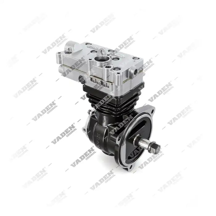
 airbrakecompressor
Rebuilding an air brake compressor is a bench job: you strip the pump to the crankcase, measure the bore, crankshaft, and bearings, then decide whether new rings, a valve plate, gaskets, and an unloader kit will restore it. A rebuild makes sense when the block and crank are within wear limits and the failure is carbon buildup, worn rings, or leaking valves; if the bore is scored or the crank is worn past spec, replace the unit instead. Air brake compressors are pneumatic pumps that feed the tanks, so the goal is a tight bore, sealing valves, and a free-moving unloader.
Decide before you disassemble
Not every tired compressor is a rebuild candidate. If the pump is pumping oil past worn rings, a ring and valve-plate kit often fixes it. But a compressor that spun a bearing, scored the bore, or ate its crank is scrap. Weigh the parts and hours against a reman or new unit before you start, because a half-finished rebuild that still leaks is the most expensive outcome. If you are on the fence, read the comparison in repair kit vs. new compressor cost.
Teardown
Work clean. Air brake components are sensitive to grit, and one metal chip in the discharge port will chew a new valve. Cap all ports as you remove lines, then:
- Mark the head-to-body and body-to-crankcase relationship with a scribe or paint pen so orientation is not guesswork on reassembly.
- Remove the cylinder head and lift off the valve plate and gaskets. Inspect the discharge cavity for carbon; heavy buildup here is a classic cause of slow charging.
- Remove the base or crankcase cover, then push each piston and rod assembly out the top of the bore. Keep them in order.
- Pull the crankshaft and bearings. Remove the unloader pistons and springs from the body, noting how they stack.
Measure everything
This is the step that decides the job. Use a bore gauge, micrometer, and feeler gauge, and compare to the manufacturer's service manual figures for your model.
| Check | Tool | What it tells you |
|---|---|---|
| Bore taper and out-of-round | Bore gauge | Whether honing and standard rings will seal, or the block is scrap |
| Piston-to-wall clearance | Micrometer + bore gauge | Slap, blow-by, and oil consumption |
| Ring end gap (in bore) | Feeler gauge | Whether new rings are correct and will seal without binding |
| Crankshaft journals | Micrometer | Bearing fit; worn journals mean replace, not rebuild |
| Valve plate flatness | Straightedge + feeler | Warp that leaks compression back into the intake |
If the bore is within limits but glazed, deglaze it with a light hone in a crosshatch pattern, then wash the block with soap and hot water to flush abrasive out of the grooves. Wipe a bore clean with a white paper towel until it comes out spotless.
Rings, pistons, and valve plate
Fit new rings to each piston and stagger the end gaps around the piston so they do not line up. A piston ring kit matched to your bore size restores compression and controls oil. The valve plate is the heart of the pump: it carries the intake and discharge valves that let the compressor build air on the up-stroke and seal on the down-stroke. Minor pitting can sometimes be lapped flat, but a warped or cracked plate must be replaced. The same goes for the small discharge valves and seats covered in the guide to valve plate and discharge valves; a leaking discharge valve is a top cause of a compressor that runs constantly and never fully charges.
Unloader reassembly
The unloader mechanism is what lets the governor take the pump off-load once the tanks reach cut-out. When the governor sends air, the unloader pistons lift the intake valves so the compressor spins without pumping. On reassembly, the unloader pistons and bores must be spotless and free-moving; a sticky unloader is why some pumps keep building past the cut-out point or fail to unload at all. Fit new unloader seals and springs from the kit, lubricate them lightly with clean assembly oil, and confirm each piston strokes fully by hand. If your kit choice is unclear, the notes on choosing an unloader kit walk through it.
Final assembly and torque
Reinstall the crankshaft and bearings, then the piston-and-rod assemblies, indexing rods to their original bores and caps. Set the crankcase gaskets dry unless the manual specifies sealant. Lay the intake and discharge gaskets, valve plate, and head in the order and orientation you scribed. Torque the head bolts in a crossing pattern in two or three steps up to the manufacturer's final value; an even crossing sequence is what seals both the intake and discharge gaskets without warping the plate. Never guess head torque, and never reuse gaskets.
Post-build test
Prime the crankcase with clean oil, then test. On a bench, spin it with a drive and confirm it builds air smoothly with no knock and no oil misting from the discharge. On the truck, cap the discharge to a gauge or watch the dash: the system should charge steadily, and the governor should cut out in the 120-135 psi range and cut back in around 100-110 psi. A fully charged system sits near 120 psi; the low-air warning should be clear well above its roughly 60 psi trip point. Watch for oil carryover into the discharge line during the first hours of run-in. If the pump builds correctly and the unloader takes it off-load cleanly at cut-out, the rebuild is good. For the reinstall procedure and line routing, see the compressor replacement guide.
Need the part, not just the answer?
OE-grade air brake compressors and repair kits, manufactured and tested to commercial-vehicle standards.
Shop VADEN partsPublished by VADEN Original. Product links point to the manufacturer’s official catalogue. Specifications are general — always confirm figures against your vehicle’s service manual.